

SAR Imagery
Synthetic Aperture Radar (SAR) satellites acquire images of the Earth’s surface by emitting radar signals and analyzing the reflected signal. As SAR satellites are continuously circumnavigating the globe, a number of SAR images can be collected for the same area over time. By processing SAR datasets, the evolution of surface deformation can be extracted as being useful for many applications.
SAR satellites
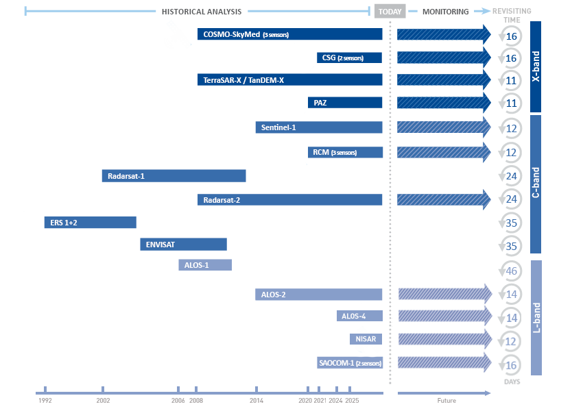
All satellites equipped with SAR sensors orbit the Earth on a near-polar orbit at an altitude ranging from 500 to 800 km above the Earth’s surface. The time taken for a satellite to re-pass over the same area is called the ‘revisiting time’. Since the launch of ERS satellites in 1992, numerous satellites have been orbiting the Earth, providing higher resolution images, faster repeat times and data redundancy for many parts of the world.
Ascending and descending orbits

All SAR satellites travel from the north pole towards the south pole for half of their trajectory. This direction is referred to as their descending orbit. Conversely, when satellites travel from the south towards the north pole, it is said to be in an ascending orbit. The same area is revisited along the two orbits. As a consequence, ascending and descending imageries are collected over the same area.
SAR image acquisition
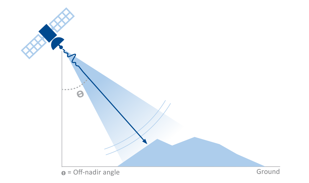
A satellite continuously emits millions of radar signals toward the Earth’s surface along the radar beam’s line of sight (LOS). The angle at which the sensor is pointed toward the Earth’s surface is referred to as the off-nadir angle (or look angle). The off-nadir angle ranges from values of 20° to 50° according to the satellite platform. This ability to vary the off-nadir angle is important to adjust it in case of hilly or mountainous terrain (potential impediments to InSAR), if the relationship between viewing geometry and terrain slope is not optimal.
SAR signal properties

Radar signals are characterized by two fundamental properties: amplitude and phase. Amplitude is related to the energy of the backscattered signal. Metal and hard objects (natural or artificial) have a high reflective quality and therefore the amplitude of the reflected signal is high. The amplitude characteristics of signals can be visualized in black and white. Phase is related to the sensor-to-target distance. It is this specific property of the radar signal that is used in estimating displacement in interferometric applications.
InSAR and DInSAR
InSAR and DInSAR: how to pass from radar images to deformation maps.
InSAR: Interferometric synthetic aperture radar

Interferometric Synthetic Aperture Radar (InSAR), or SAR Interferometry, is the measurement of signal phase change between two images acquired over the same area, at different time. When a point on the ground moves, the distance between the sensor and the point changes and so the phase value recorded by the sensor will be affected too.
The change in signal phase (Δφ) is expressed by the equation below:

Where λ is the wavelength, ΔR is the displacement in the Line Of Sight (LOS) and α is a phase shift due to different atmospheric conditions at the time of the two radar acquisitions.
Interferograms

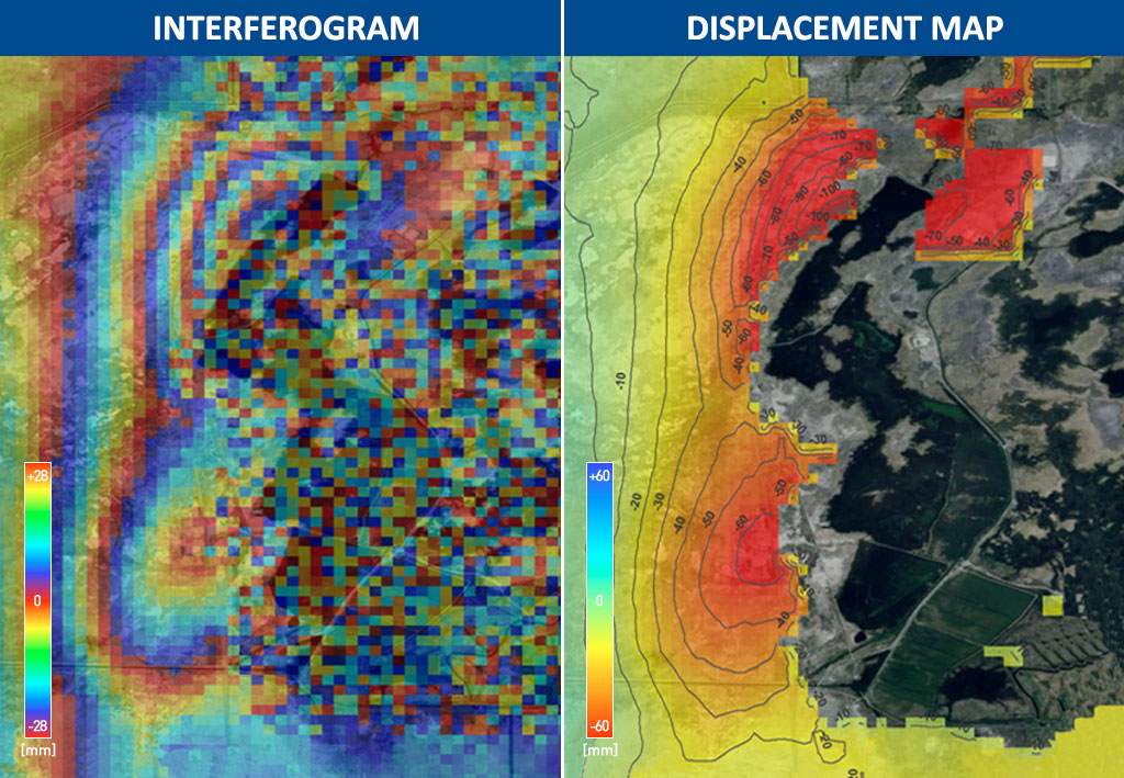
An interferogram is the difference of the phase values corresponding to a certain area, i.e. it is a digital representation of a change in surface displacement. It corresponds to a matrix of numerical values ranging from -π to +π (phase variations) and it can be converted into a map – the easiest way to observe whether or not motion has occurred over a certain area.
Phase signal contribution
Interferometric phase (Δφ) is impacted by four contributions: 1) topographic distortions arising from slightly different viewing angles of the two satellite passes (t), 2) atmospheric effects (α) arising from the wavelength distortions by the moisture-bearing layer, 3) any range displacement of the radar target (ΔR), 4) noise (decorrelation effects).
These factors are given in the equation below:

It is difficult to remove all the contributions to phase but the range displacement using a single SAR interferogram.
DInSAR: Differential InSAR
DInSAR is not a tool for accurate displacement measurements, but it is useful in identifying footprints of progressing movement. Differential interferometry or DInSAR is interferometry itself. The only difference is that topographic effects are compensated by using a Digital Elevation Model (DEM) of the area of interest, creating what is referred to as a differential interferogram. This can be expressed as:

Where ε is the contribution to phase arising from possible errors in the DEM. Whenever noise levels are low (i.e. decorrelation effects are negligible) and the phase contribution due to the local topography is accurately compensated for (i.e. ε is also negligible), the interferometric phase Δφ can be simplified as follows:
Where ΔR is any range displacement of the radar target and α is the atmospheric contribution to the phase shift. Once a differential interferogram has been prepared, a deformation map can be created for all areas that are coherent, as shown in the figure.
Interferograms are very useful to monitor strong motion phenomena, such as earthquakes or volcanoes.
SqueeSAR®
The most advanced algorithm for surface displacement detection, SqueeSAR® is the latest InSAR technique developed by TRE ALTAMIRA for the detection of millimetre surface displacements, improving our previous PSInSAR™ algorithm.
PSInSAR™
Permanent Scatterers Interferometry (PSI) techniques first emerged in 1999 when the Polytechnic University of Milan (POLIMI) produced and patented its PSInSAR™ algorithm.
PSInSAR™ is a significant evolution of conventional InSAR whereby:
- A multi-image data set is used (minimum of 20-25 images).
- Atmospheric and orbital errors are essentially removed.
- Sub-pixel radar reflections are analyzed.
- Linear and non-linear deformation patterns are identified.
- Time histories of movement are generated for every radar target (PS).

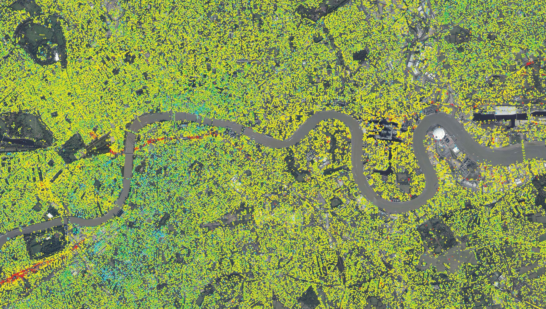
The use of multi-image datasets makes it possible to identify stable reflectors, referred to as Permanent Scatterers, or PS, which are points on the ground that return stable signals to the satellite sensor (e.g. buildings, metallic objects, pylons, antennae, exposed rocks), allowing surface displacement velocities to be measured with millimeter accuracy. The PSInSAR™ algorithm was licensed to TRE for worldwide application.
SqueeSAR®
Since its introduction in 2010, SqueeSAR® has challenged the industry standard by identifying many more ground points, hence increasing the overall understanding of ground displacement occurring in an area of interest.

SqueeSAR® is the only algorithm that we offer to clients, providing a significantly increased coverage of ground points, especially over non-urban areas. As it was standard with the previous PSInSAR™ algorithm, SqueeSAR® continues to identify PS but it also exploits spatially distributed scatterers (DS). Whilst PS usually correspond to man-made objects, DS are typically identified from homogeneous ground, scattered outcrops, debris flows, non-cultivated lands and desert areas.
SqueeSAR® results
SqueeSAR® results can be visualized as:
- Average velocity map (for an overview of ground motion over the entire area of interest)
- Displacement time Series, for each measurement point.
The position of each measurement point (latitude, longitude, elevation) and its quality values (standard deviation and coherence, which give an idea of how reliable each individual point is) are provided within the SqueeSAR® database. The database can be easily imported in a GIS software and visualized or delivered in our web platform TREmaps®.

In addition to principle results, the following SqueeSAR® maps can also be delivered according to the movement expected or any interest in particular features:
- Cumulative displacement, to map the total displacement that has occurred from the first satellite image acquisition to any sequential acquisition (from the second to the last).
- Average acceleration, to highlight areas affected by increasing or decreasing rates of velocity
- Periodic variation (seasonality), to highlight areas that exhibit cyclic behaviour
- Differential displacement, to allow displacements, that have occurred between two single satellite acquisitions (two discrete time periods), to be mapped and analyzed.
What can be measured?
Single satellite geometry

What is actually measured in interferometric applications is the projection of a target’s motion onto the satellite’s Line Of Sight (LOS). However, the LOS motion can often differ noticeably from the real value of motion, especially in cases where the ground motion is not vertical.
Double satellite geometry: true vertical and horizontal east-west displacement

By using both ascending and descending imageries, it is possible to obtain an accurate estimate of the true vertical and east-west components of the motion.
Precision
The most important factors impacting on measurement quality are:
- Spatial density of the measurement points (the lower the density, the higher the error bar)
- Quality of the radar targets (signal-to-noise ratio levels)
- Climatic conditions at the time of the acquisitions
- Distance between the measurement point and the reference (REF)
- Number and temporal distribution of acquisitions
For SqueeSAR® measurements, the standard deviation refers to the average displacement rate with respect to the reference point (as in traditional geodetic networks, measurement precision decreases as distance from reference point increases).
Considering a dataset of at least 30 scenes covering a 2-year period, a measurement point (MP) located less than 1 km away from the REF has a typical standard deviation value lower than 1 mm/year. The single displacement value precision is generally within ± 5 mm (see table below).
| Displacement (LOS) | Average displacement rate | Single measurement |
|---|---|---|
| Precision | < 1 mm/year | < 5 mm |